Marshall clone
Description of a 50 Watt guitar amplifier with is a look-alike of an amplifier of the brand MARSHALL.
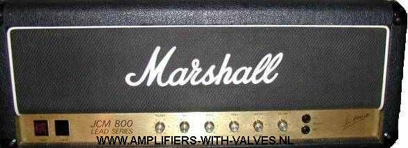
The next picture is a photo of a real Marshall. The inspiration of this design.
This amplifier uses also the EL34 as the output valve. In this case only 2 tubes are used.
Therefore the max output power is 50 Watts. At the end of this chapter there is a schematic drawing of a 100 Watts amplifier.
It's possible to use the same chassis. Only a few more holes have to be drilled into the chassis.
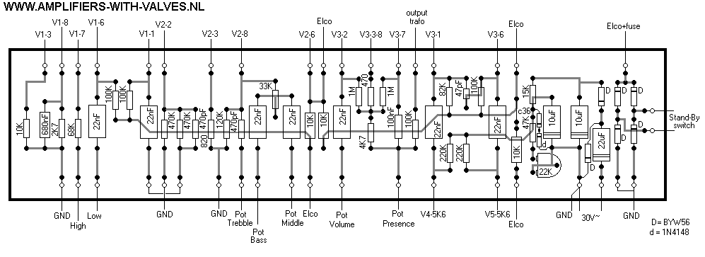
Next drawing is the schematic diagram of the 50 Watt one.
Schematic diagram
The description is only the amplifier. The housing can be made out of wood or MDF. I don't have a drawing of that part. The first you have to make is a chassis. I used an aluminium plate of 810 x 300 mm and 1 mm of thickness.
You must use the numbers written into the drawing, because the drawing is not scaled. The best way is to buy all components first and than start building.
The possibility is there that you can not buy the same components I use, and than the holes are not right. The mounting holes of the printed circuit board, tube holders, elko's and transformers are not drawn. These holes are depending on the components you will get. Next the drawing of the chassis.
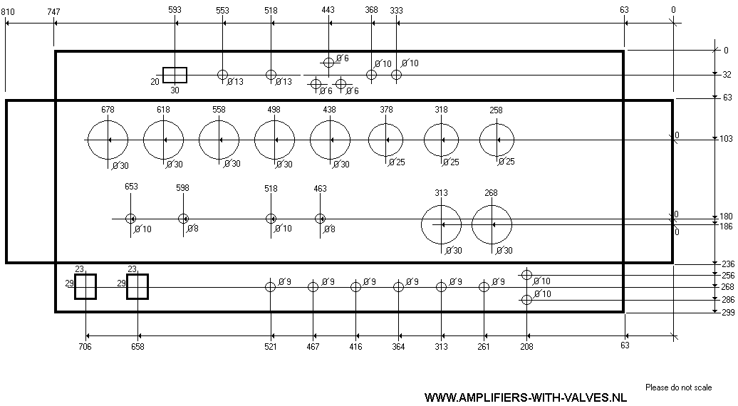
Drawing chassis
When ready drilling holes you can bent over the edges over 90 degrees. I welded the 4 corners, but you can put the corners together with screws and bolds of M3.
If this is done we can mount the tube sockets, Elko's and transformers to the chassis. Also the Mains and the standby switch, the pot meters and plugs can be placed in the chassis.
As filter choke I used an old transformer of 66 x 55 x 28 mm. I did 2750 windings of 0,3mm copper wire on the coil form. When ready I drilled then the holes for the choke in the chassis and a hole for the connection wires.
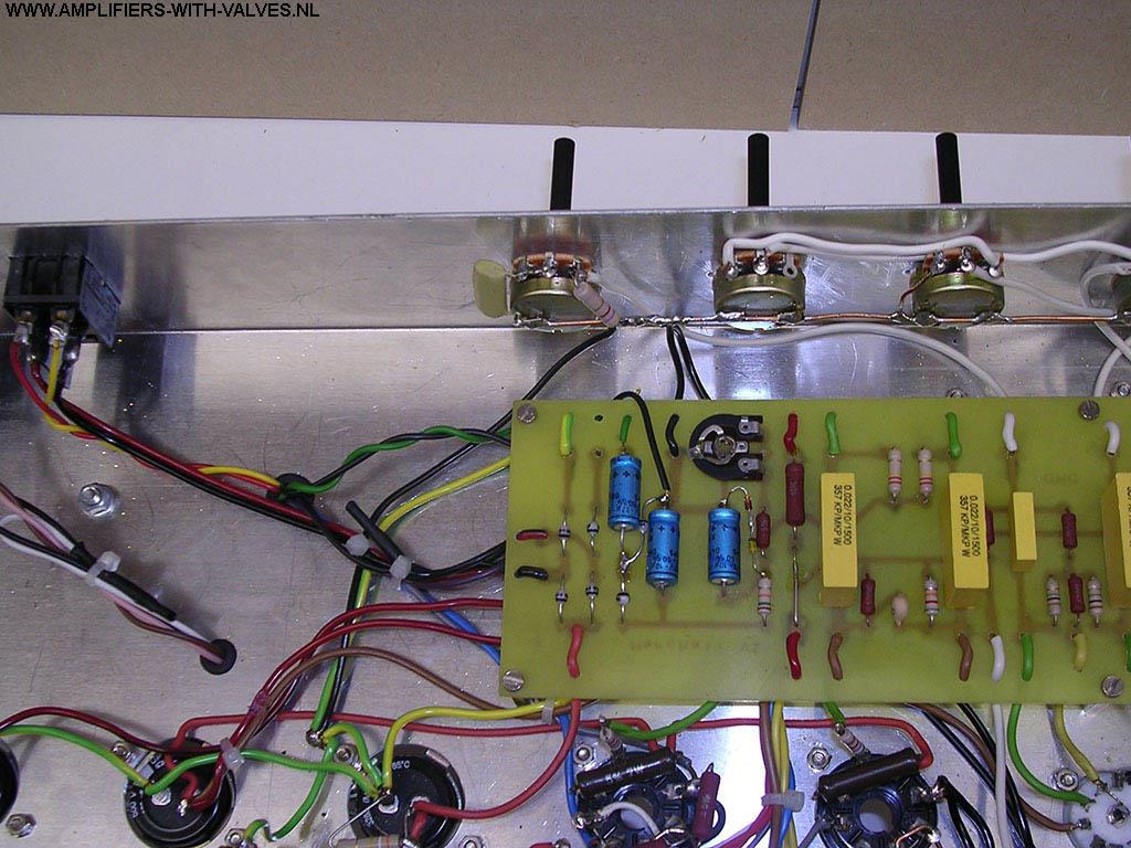
Then the time came for assembling the printed circuit board with resistor, capacitors and diodes. The wiring of the printed circuit board are in grey as they are at the bottom side of the printed circuit board.
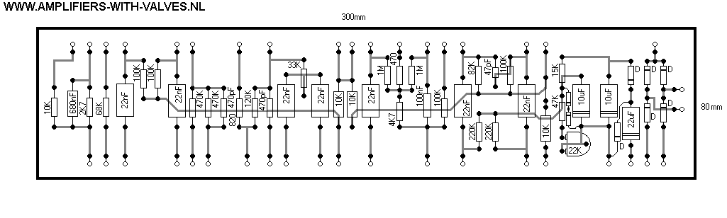
Printed circuit board
In the circuit board and the chassis you have to drill 6 holes for putting the board on distance parts and the chassis.
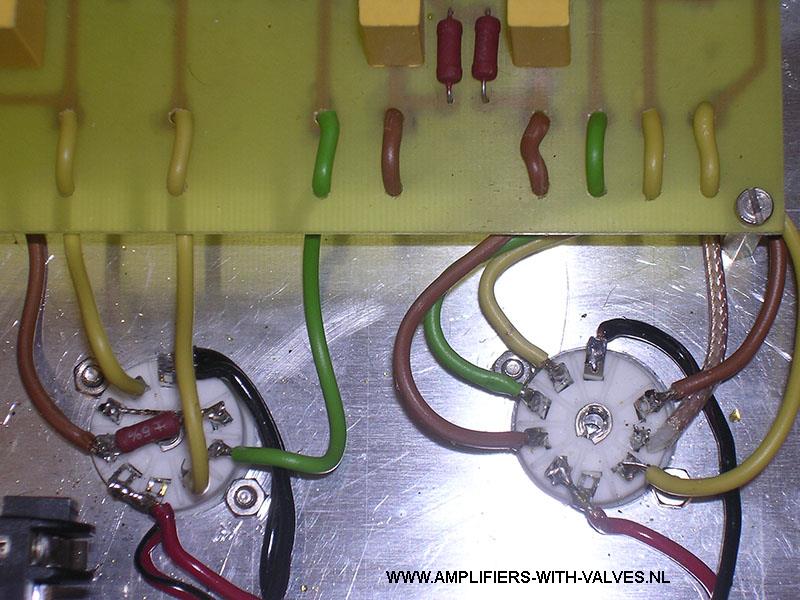
When ready mounting this board in the chassis you can mount the wires from the board to the tube sockets. Next picture is where the wires are going to.
Wiring diagram form circuit board to tube sockets and pot meters. The text near the small holes is where the wires are going to.
The photos placed under this text are for illustrating this part of the building of the amplifier how I did it.
When wiring the ground (GND) wires, look good where these are going to. If doing this different the possibility is there that you make a mistake and the amplifier can hum.
There are 2 ground points. One for the analogue input signal and one for the supply return. At the end, these 2 points are coming together to one point.
The photo's will tell.
The complete amplifier:
Front view
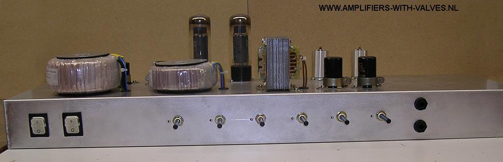
Rear view
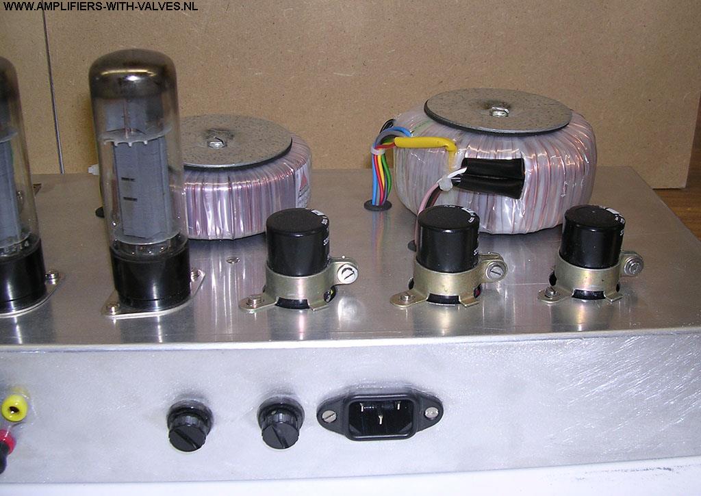
Detailed mains transformer, output tranformer and elco's.
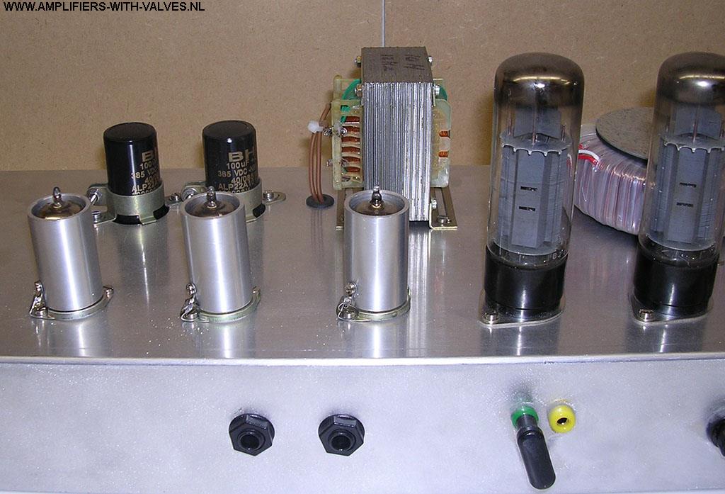
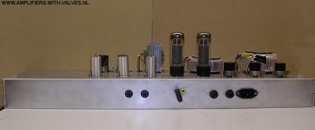
Detail of the choke, other elco's and the tubes.
Mains and standby switch.
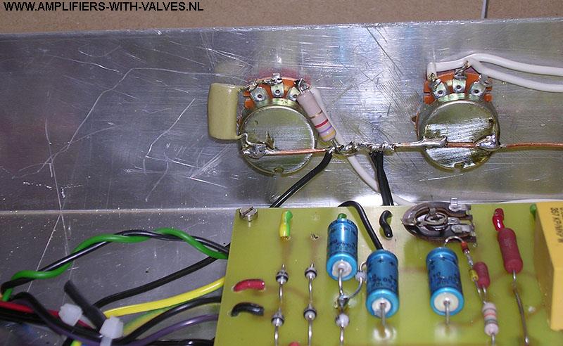
Presence pot meter and analogue ground point. The analogue ground point is a copper wire that is soldered at the housing of all pot meters. The pot meters are isolated from the chassis. The pot meters I used have plastic front sides.
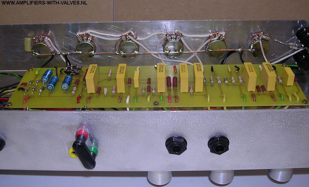
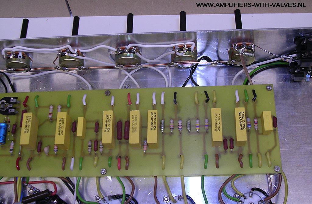
Here the view of all pot meters and there connections.
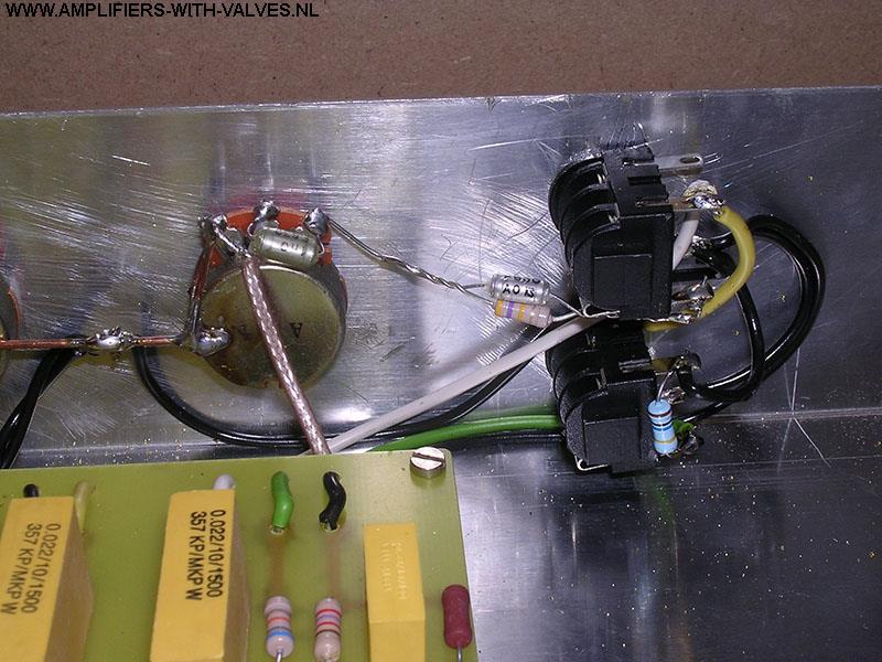
As you can see, not all components are on the circuit board, some are connected in the air. For better servicing and overview I used different colours of wires. Yellow for the cathodes. Brown for the anodes. White is going to the pot meters, and the green colour for de grid's Red/black for the filaments, the wire I use for this purpose is a double wire.
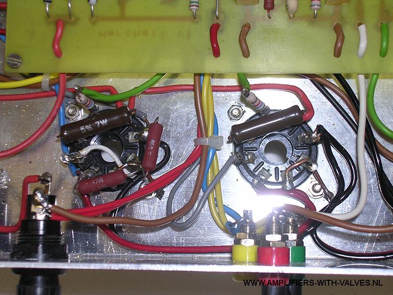
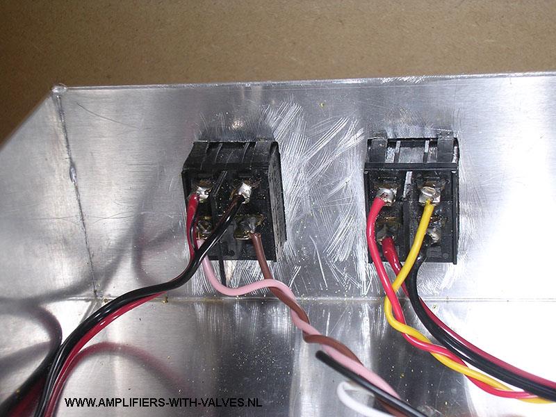
This is a detail of the power tubes, and also a detail of the fuse. (0,5A for the DC voltage).
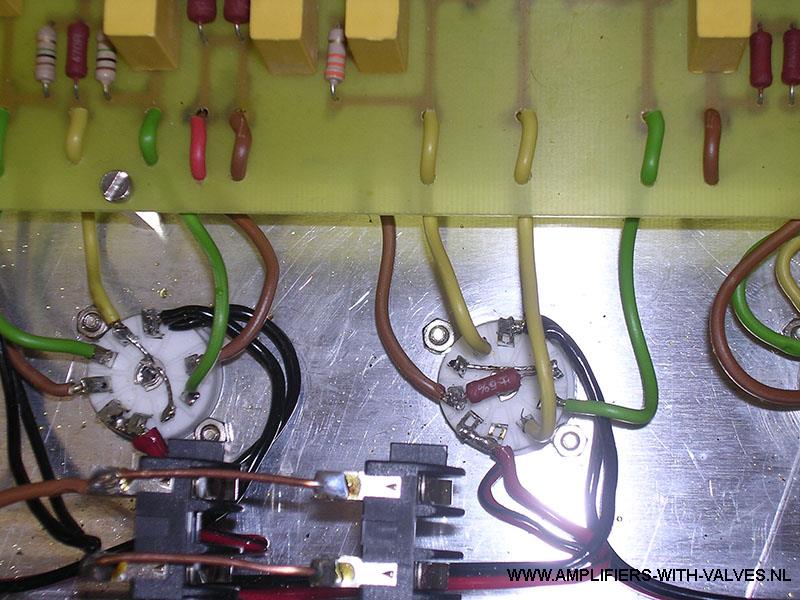
Each power tube has its own ground. Pin number 1 and 8 are put together and soldered to a solder pin./p
Near the left power tube the 2 resistors of 47 ohm are grounding the filaments.
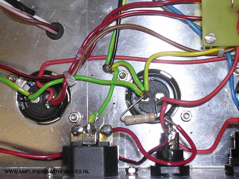
Near the first Elko the mains ground is connected. Yellow-green is the colour of this wire. All zero points of all Elko's are coming together here. The black wire is the wire coming from the pot meters. Next some more detail photo's of the amplifier.
Details of the circuit board and it connections.
This schema is the 100 Watts version of this amplifier. The drilling has to be modified for 2 more EL34's The numbers written near the transformers are the order numbers of these parts if ordered by AMPLIMO.
100 Watt version of the amplifier.
If more info is needed, sent an email to el64xx(@)gmail.com. Email adress without ( ).