Big power amplifier
This amplifier is designed by myself and built together with a friend which is very good in the mechanical part of the design. Each amplifier is built with 4 times the EL34 in PP class B mode. The complete amplifier consists of 6 power modules connected together for a very high output power. The application of these amplifiers was first for PA purposes in motorcross events. First a photo of the complete amplifier, which was split into 2 cabinets, because of its weight. Each cabinet contains 3 power modules connected in parallel and can be switched on separately. Photo 1 is the overview of the two cabinets.
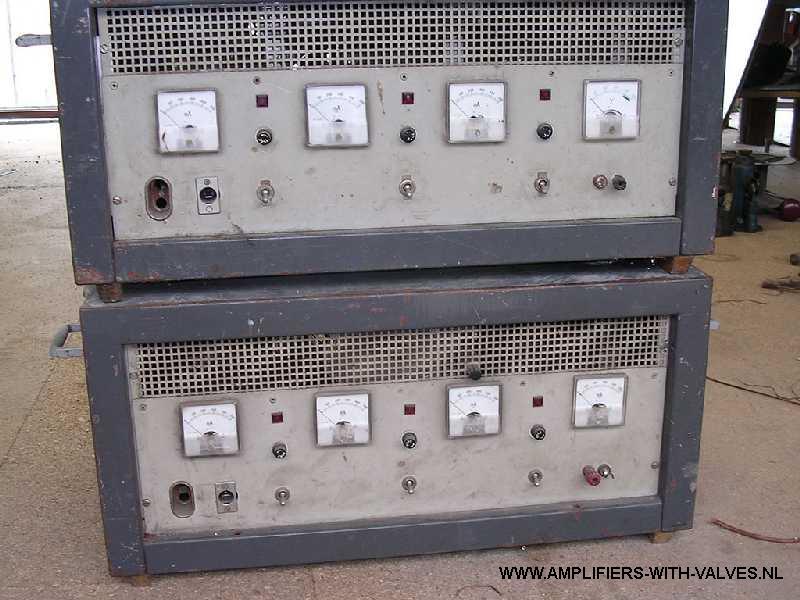
Photo 1
Photo 2 is the front plate of 1 cabinet. The mA meters give the value of the anode current of each module. The voltmeter in the right position gives the loudspeaker line voltage up to 200 volts. You can also look at the separate power on switches. Each amplifier can be switched on or off in case of to much power or a broken amplifier.
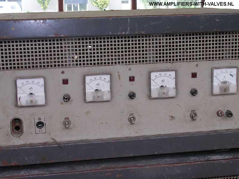
Photo 2
This complete system is a PA amplifier with a power of 1200 Watts continues and 2400 Watts peak power with a constant voltage line output to the speakers. It can also be used as a 2 times stereo amplifier of 2 x 600 watts. For use as a PA stage amplifier for rock bands or other musicians.
Here some photos of the rest of the cabinet.
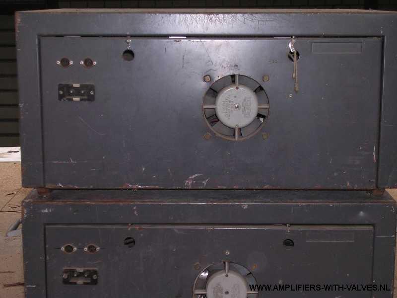
The dust is very good to see, but still working with no problems. At the inside you see the 3 separate power amplifiers. The connection of the mains, speakers and the input signal is made by plugs, so its easy to take one out if necessary.
How its built:
In this part of the story you can see how one amplifier is built.
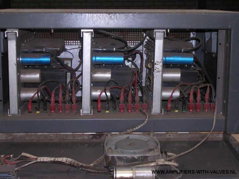
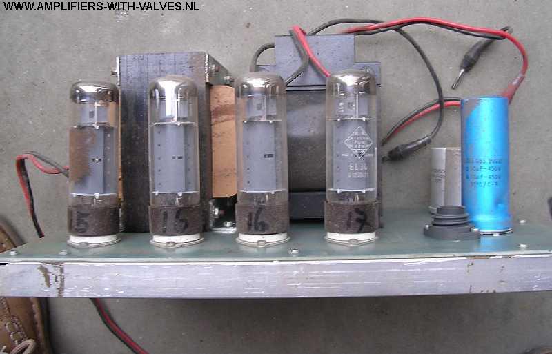
Photo 4 is the front and rear view of one power stage.
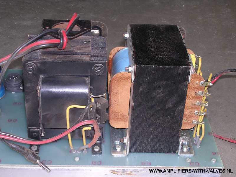
One complete amplifier is built on an aluminium frame with epoxy glass fibre print board as chassis for the transformers, electrolytic capacitors, valves and plugs. The next photo shows us the inside or the bottom view of the amplifier.
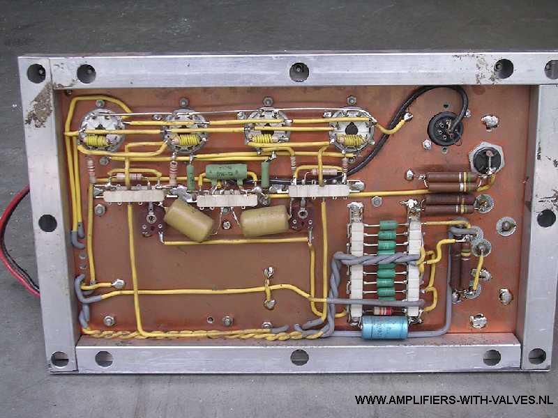
Photo 5
Construction data:
Drawing 1 is the data of the chassis where the holes are situated and other components.
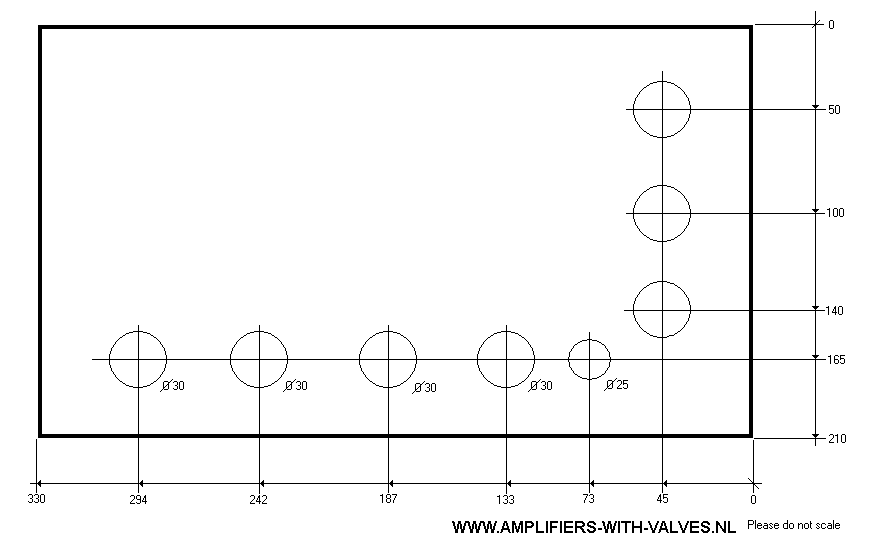
Drawing 1
Drawing number 2 is the schematic diagram of one power amplifier. This whole system uses 6 of these amplifier units. You see that each power unit consists of a power supply for the 4 EL34 tubes, a power supply for the bias of the tubes and an output transformer. The data of the power transformer and the output transformer are written in the diagram.
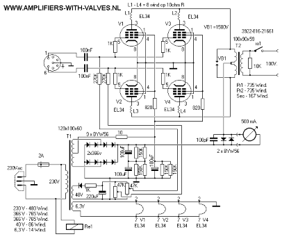
Diagram 2
The bias of the 4 tubes EL34 is set to 20 mA each, so the quiescent current for one amplifier is about 80 mA. The next drawing is the drawing of one complete cabinet. In this cabinet is place for 3 of the above power amplifiers the mains switches, a mains control lamp, the main socket, the input connection and the loudspeaker output connection.
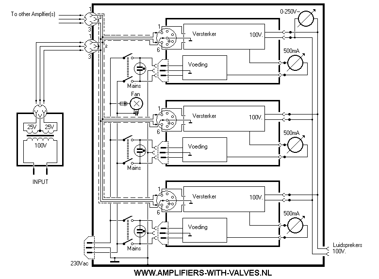
Diagram 3
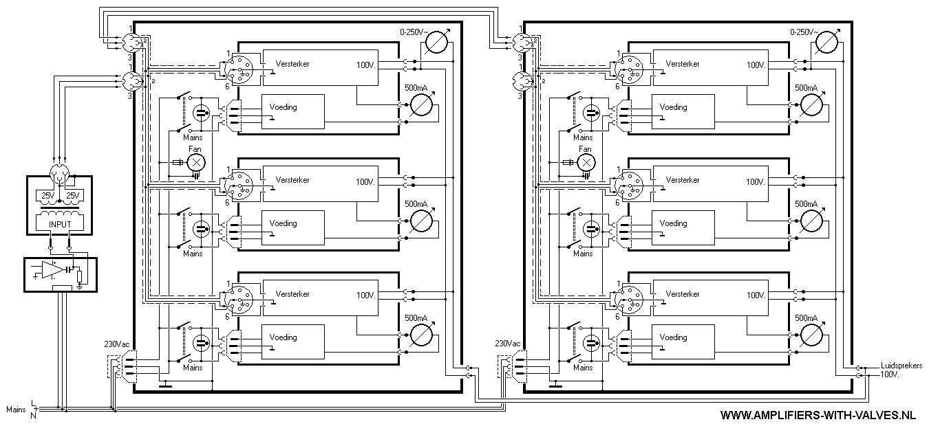
And here the complete connection of the two amplifier boxes, how they were connected to the small controle amplifier (5 watts), the mains and the speakers.
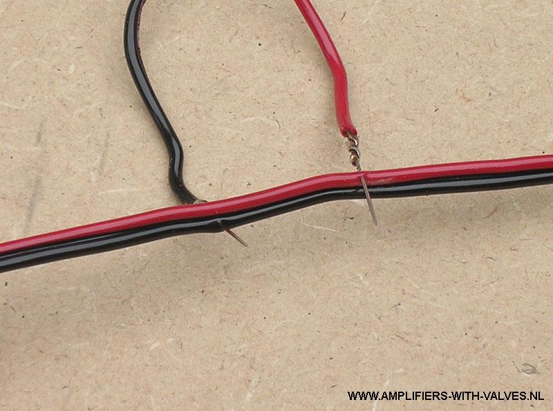
The next two photos gives an example how to connect the several speaker cabinets to the output line of the power amplifier.
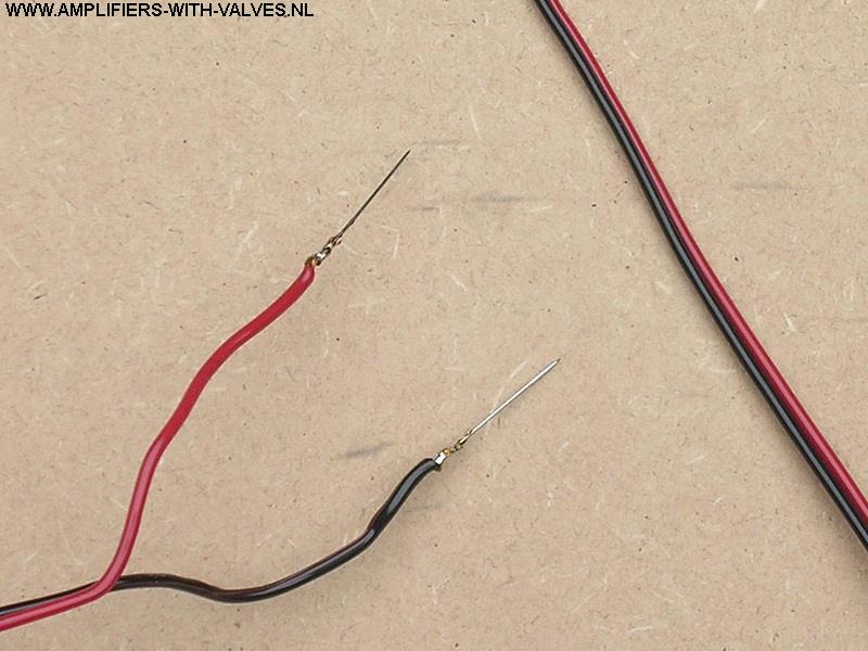
This photo gives a detail of the line cable and a detail of the speaker cabinet cable with needles.
This photo gives a detail of the connection of the speaker cabinet to the audio power line.
If more info is needed, sent an email to el64xx(@)gmail.com. Email adress without ( ).